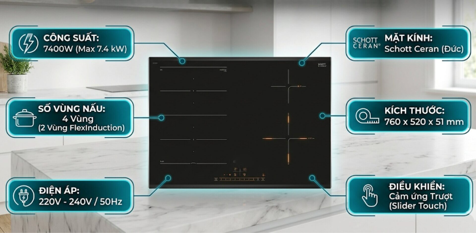
The electrical circuit diagram of the induction cooker below is the most complete and detailed repair document regarding the induction cooker circuit, the cooker board, the basic electrical circuit diagram of the induction cooker,… from professionals who specialize in researching, repairing, assembling, and developing induction cookers. If you need information on this topic, below is the most comprehensive document you are looking for.
What does the basic electrical circuit diagram of the induction cooker include?
Induction cookers are one of the modern cooking devices that are no longer unfamiliar to many people. Because of their luxury, class, safe and clean cooking, and energy-saving benefits. Especially, the durability and lifespan of the cooker can reach several years.
However, everything has a lifespan, and continuous use will eventually lead to malfunctions that need repair or warranty. If you want to know where the induction cooker is faulty and how to repair it, you need to learn about the induction cooker board, the microchip structure of the induction cooker, and the basic electrical circuit diagram of the induction cooker to accurately identify the cause and address it promptly, saving time and ensuring effectiveness.
| What is electromagnetic induction? Applications of electromagnetic induction
Let’s take a look at what the basic electrical circuit diagram of the induction cooker includes?
1 – Induction cooker board
The main board: plays the role of an electronic circuit board that determines the entire operation of the induction cooker. This is considered the most important component in the electrical circuit diagram of the induction cooker.
Most basic electrical circuit diagrams of induction cookers contain the main board. On this board, there are many important electronic components, including resistors, capacitors, IGBT power transistors, inductors, current transformers, variable resistors, temperature sensors, pulse transformers, bridge diodes, ICs, etc.
The induction cooker board is very easy to identify and quite visible as it occupies the most area in the electrical circuit diagram of the induction cooker with a large size.
Depending on the type of cooker, the main board may vary in size. For example, the electrical circuit diagram of the Midea induction cooker will have a different circuit than the Sunhouse cookers. The diagram for single induction cookers will differ from those for double or 3-4 cooking zones. This difference may also be due to each induction cooker diagram using different types of components.
For single induction cookers, the small size usually has a single-layer printed circuit board. In contrast, double induction cookers or those with 3-4-5 cooking zones have larger main boards because they are made as double-layer printed circuit boards. However, the diagram for 2 cooking zones tends to be more complex.Some induction cooker repair documents may not clearly specify these differences. However, through practical experience and extensive research, we have drawn insights about the induction cooker component diagram.
2 – Induction cooker control board
An essential component in the induction cooker circuit is a board responsible for displaying the operational modes of the cooker. It is called the induction cooker control circuit, which functions to receive user commands through buttons. These can be slide switches, mechanical knobs, or touch controls.
The control board is present in most basic electrical circuit diagrams of induction cookers. Typically, these multifunction induction cooker boards have a simpler structure than the main board. You can easily recognize the main components, which are LED indicators and function selection buttons for the cooker.
If you are using older induction cookers, the buttons are still mechanical buttons. In contrast, modern induction cookers commonly use touch buttons. A specific example for you to see is the Media induction cooker board.
3 – Coil
The coil, also known as the induction heating coil. To better understand this specific heating component, you should refer to the section What is an induction coil? Understanding the types of induction heating coils to recognize the quality of the copper coil. Most modern induction cookers use a heating coil made of tightly wound copper wires. The coil is circular with a diameter ranging from 9 to 25 cm, depending on the cooker.
The coil is an indispensable component in the electrical circuit diagram of the induction cooker. Without this component, the induction cooker cannot cook.
The induction heating coil serves as the component that generates the magnetic field to heat the pot placed on the cooker. The process of converting electrical energy into thermal energy occurs through the induction heating coil. Typically, this component is placed under the glass surface and has markings as circular diameters for you to place pots and pans on.
Of course, the principle diagram of the induction cooker is not like that of an infrared electric cooker, so this coil does not get hot but only emits a very strong magnetic pulse that heats the induction pot.
Similar to the induction cooker control board, the number of coils depends on the type of cooker. A single cooking zone induction cooker (single induction cooker) will only have one coil. The number of cooking zones corresponds to the number of coils present in the induction cooker circuit.
4 – Cooling fan
This type of fan is also known as the induction cooker cooling fan. Although it is a minor detail, it plays a crucial role in the electrical circuit diagram of the induction cooker. It functions to maintain the stable operation of the cooker.
When the induction cooker operates, the electronic components generate heat, causing the cooker to become hot, making the electronic components very susceptible to damage if operated at high temperatures continuously. Therefore, the cooling fan is the solution to cool the entire induction cooker board.
The 18v induction cooker fan operating on direct current is the most common type equipped in most basic electrical circuit diagrams of induction cookers. The cooling fan needs to be plugged in the correct direction (+), (-) for it to operate. This component has a very long lifespan, rarely experiencing electrical failures, mainly mechanical failures such as broken blades, dry oil, loose screws, etc. In case of a malfunction Induction cooker fan not running, the temperature sensor of the cooker will immediately send a command to cut the circuit to protect the power IC and the power transistor.
These are the four basic parts in the basic electrical circuit diagram of the induction cooker that you need to understand. Additionally, Kocher’s induction cooker repair document also compiles notes on the terminology and functions of each component below.
Notes on terminology and functions of components in the basic electrical circuit diagram of the induction cooker
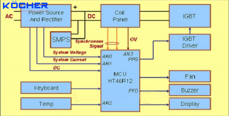 Basic electrical circuit diagram of the induction cooker
-
Power Source And Rectifier – Power supply and rectifier circuit
This is the input component of the induction cooker control circuit, which appears in most induction cooker circuits. It includes components such as fuses, high-frequency noise filter circuits, overcurrent protection, and rectifier diodes converting to DC voltage.
-
SMPS – Switch Mode Power Supply
SMPS is the abbreviation for Switch Mode Power Supply. The switching power supply is responsible for generating DC voltage levels. This component provides DC voltage for other parts of the induction cooker, including:
+ 5V DC voltage for the MCU processing unit.
+ 12V voltage for the cooling fan.
+ 15V – 18V voltage for the pulse amplifier stage (IGBT Drive)
-
Coil Panel – Induction cooker coil
Each induction cooker is equipped with a coil panel. This coil serves to generate a magnetic field, which will create eddy currents at the bottom of the pot, instantly heating the pot and cooking the food.
-
IGBT – Power transistor with G-C-E legs
In the previous article, Kocher shared detailed information about power transistors in the article What is IGBT? Understanding the structure and how to measure IGBT in induction cookers. The IGBT power transistor is the main power-consuming component of the cooker. When assembling the circuit or installing, technicians must strictly follow the induction cooker wiring procedure to ensure that the load current supplied to the induction coil through the power transistor is always stable. It is responsible for quickly switching high frequencies and generating high-frequency currents. This current flows through the induction coil of the cooker, thereby generating a magnetic field within a few millimeters of the glass surface of the cooker and heating the bottom of the pot.
-
IGBT Drive – Pulse amplifier stage
IGBT Drive is responsible for amplifying the electrical pulse optimally. From 15 to 18V before being sent to the G leg of the IGBT power transistor.
-
Keyboard – Buttons
The buttons on the control panel are the settings that users commonly use when cooking. The control and display panel is part of the induction cooker control circuit. The CPU is responsible for controlling the operation of these buttons.
-
Temp – Temperature sensors
Modern induction cookers today are equipped with 2 temperature sensors as shown in the induction cooker circuit diagram.
One sensor is attached to the bottom of the cooking utensil to monitor the temperature of the pot, pan, or wok you are using. If during cooking, the pot or pan runs out of water, the temperature will rise rapidly, and the induction cooker will become very hot. The cooker may emit a warning signal with error code e,,. The CPU must cut off the power (the induction cooker may turn off automatically) to prevent the power indicator from operating. This helps users cook more safely and save energy.
The other sensor will be attached to the screw of the power transistor to monitor the temperature of the IGBT power transistor. In case the power transistor overheats, the CPU will automatically cut off the oscillation sent to the IGBT power transistor to turn off the voltage. This helps protect the components equipped inside the induction cooker circuit.
-
MCU (Microcontroller Unit)
The microcontroller is also considered the most important component in the induction cooker board. The MCU operates based on a pre-programmed principle from the original program. This microcontroller will work after receiving data from user operations set on the control panel. Then the MCU will emit electrical pulses to control the operation of the power transistor. All requests will be received and processed by the microcontroller according to those commands.
The timing and width of the emitted pulses can be changed by the programmed software.
For example, when you cook and set the cooking temperature to high, the emitted pulse will be wider, and the IGBT’s on-time will increase. Conversely, when you set the temperature to decrease, the emitted pulse will be smaller, and the IGBT’s on-time will decrease.
The microcontroller is even smarter as it can detect whether there are cooking pots on the cooker. If there are no pots or the pots are empty, it will automatically turn off the operation of the power transistor.
The MCU also has the function of controlling the temperature of the pot and the power transistor. If the temperature is too high, it will “command” the power transistor to take a break to protect the power transistor and other components inside the induction cooker circuit.
-
FAN – Induction cooker cooling fan
As we have shared about the induction cooker fan, it is responsible for cooling the IGBT and the components inside the induction cooker circuit.
-
Synchronous Signal – Synchronous signal
In the electrical circuit diagram of the induction cooker, the synchronous signal component is indispensable. This signal is emitted from both ends of the working coil of the cooker, assisting the CPU in detecting the presence of pots and pans placed on the cooktop.
-
Buzzer – Buzzer
The buzzer here refers to the beeping sounds you often hear when cooking. It serves as a warning and notification for users to easily recognize when pressing adjustment buttons or when setting timers. You will also hear these sounds when the induction cooker encounters error codes from e0, e1, e2,… to e9.
-
Display – Display
Any electrical circuit diagram of an induction cooker is equipped with displays or a system of red or green LED lights. The LED colors will indicate to users the cooking modes and temperatures of the cooker.
-
System Voltage – System Current – Voltage and current of the cooker.
System Voltage – System Current are signals for the CPU microcontroller to know the voltage and current status of the cooker during operation.
-
OC (Over Current) – Overcurrent warning
When the cooker operates at high power levels, OC (Over Current) will report overcurrent to the CPU microcontroller, which will process it by putting the cooker on hold, preventing damage.
-
OV (Over Voltage) – Overvoltage warning
OV (Over Voltage) plays an important role in the induction cooker circuit. It is the component that constantly monitors the overvoltage status on the coil. It sends a signal to the CPU microcontroller immediately if the induction cooker experiences overvoltage on the coil, prompting the CPU to put the cooker on hold to avoid high voltage damage.The electrical circuit diagram of the induction cooker that Kocher has just shared is an extremely detailed repair document that we have compiled. We hope that the information above will help you understand the basic electrical circuit diagram of the cooker most effectively.
Köcher is proud to be the pioneering unit in Vietnam bringing German technology into induction cooker products.