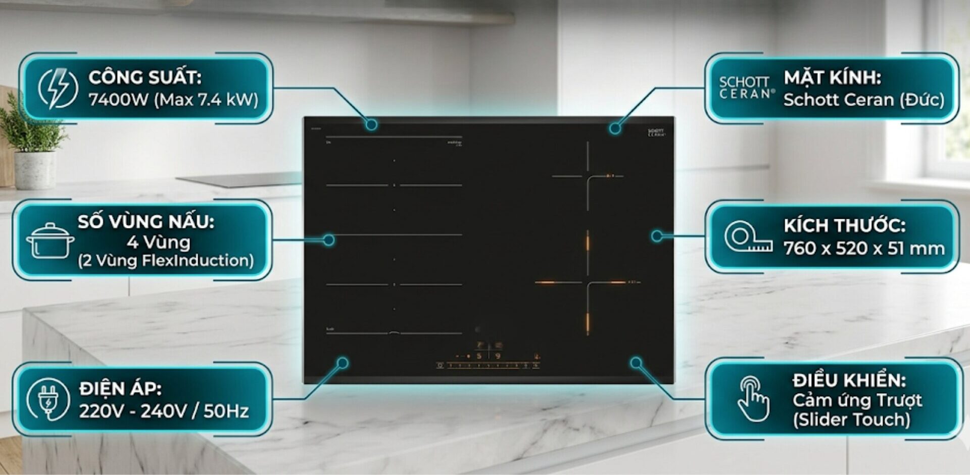
Connecting the induction cooker’s wiring correctly is an important factor that helps the device operate stably and durably over time. The following article will provide detailed instructions on how to connect the induction cooker with 5 wires, 4 wires, and 3 wires according to the standards, making it easy for you to successfully and safely implement it at home.
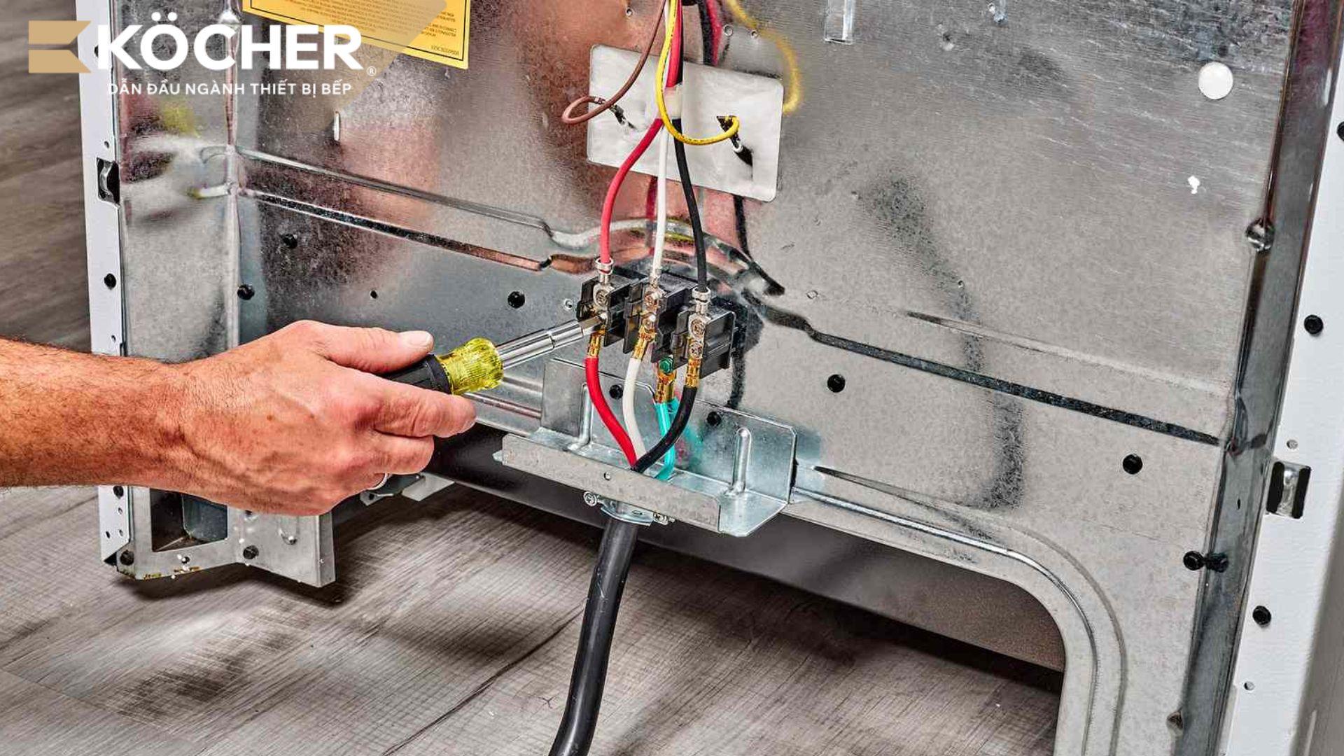
The common color code for electrical wires is as follows:
| Symbol | Wire Color | Function |
| L | Can be various colors (Brown, Black, Red, Gray, Orange…) but not Sky Blue, White, and Green with yellow stripes. |
This is the phase wire (live wire), carrying voltage from the source to power the device. When connecting, it is necessary to identify it correctly to ensure the device operates and avoid the risk of short circuit. The induction cooker’s power wire may have one or more phase wires depending on the type of cooker (single phase or three phase). Note: If you see a Black wire, it is likely a phase wire. |
| N | Sky Blue (Blue) or White | This is the neutral wire (return wire), which serves to return the current back to the source, helping to complete the circuit and maintain stable operation of the device. |
| PE | Green with yellow stripes (Yellow Green) | This is the grounding wire (earth wire), which functions to carry leakage current to the ground in case of a fault, helping to protect users from the risk of electric shock. |
Preparing tools for connecting the induction cooker wiring
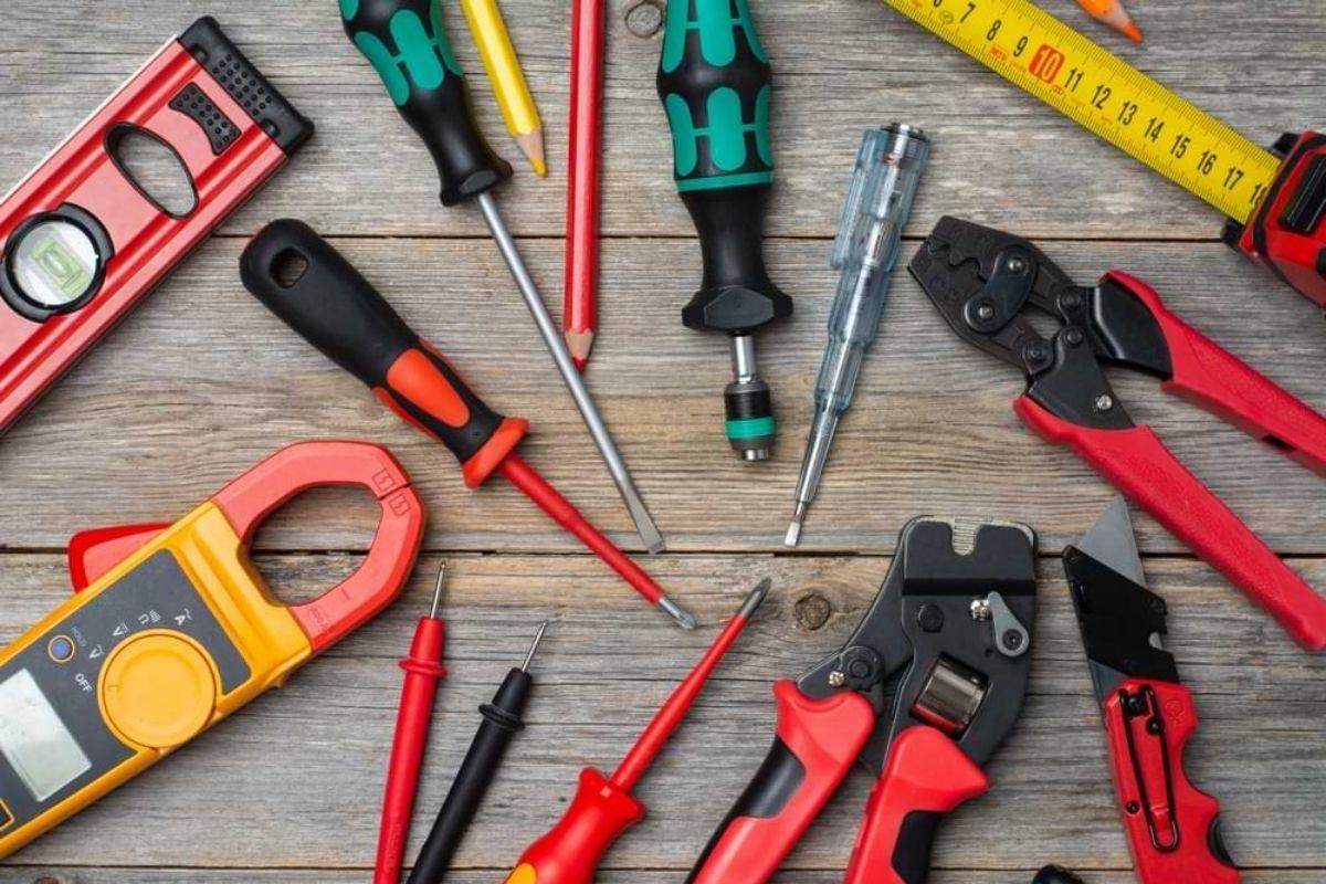
To ensure the wiring of the induction cooker goes smoothly, technically correct, and safely, you need to equip yourself with all the necessary specialized tools. Below is a list of essential items:
- Voltage tester (1 piece): An essential tool to accurately identify the live phase (L) and neutral wire (N) of the household power supply, ensuring safety before proceeding.
- Wire stripper (1 piece): Helps quickly strip the plastic sheath without damaging or cutting the copper strands, maintaining the cross-section for electrical conduction.
- Multi-purpose screwdriver (2 pieces – Phillips and flat head): Used to tighten the wire ends into the terminals of the circuit breaker; choose one with an insulated plastic handle.
- Crimping tool (1 piece – optional): Used to firmly crimp the terminal onto the wire core, creating a durable connection and preventing arcing at the joint.
- Circuit breaker (1 piece): Choose according to the cooker’s power (For example: a 4000W cooker uses 25A, a cooker over 4000W uses 30A – 45A). Since the cooking current of this device is very high, it is recommended to limit the use of Common sockets for induction cookers and replace them with specialized circuit breakers as the safest solution.
- Electrical tape (1 roll): Heat-resistant type, used to securely cover exposed joints.
- Terminals (3 – 5 pieces): Especially important for 4-wire, 5-wire cookers to ensure the best electrical contact area.
- Power supply wire: Depending on the cooker’s power, for 3500W – 5500W choose wire with a minimum cross-section of 4mm², for 5500W – 7000W choose wire with a minimum cross-section of 6mm², for over 7000W choose wire with a minimum cross-section of 10mm².
- Additional grounding wire (2 – 3 meters): Auxiliary wire used to connect the cooker’s body to the grounding system, ensuring absolute safety in case the device leaks electricity.
- Electrical conduit/Conduit (1 roll – optional): Used to cover the outer layer of the power wire when running underground in the kitchen cabinet, effectively preventing rodent bites and moisture.
- Insulated gloves (1 pair): Gloves made of natural/synthetic rubber, helping to prevent electric current from passing through the body when working with electrical devices, ensuring maximum safety.
Detailed instructions on how to connect the induction cooker wiring for each type of wire
Depending on the number of power wires of the induction cooker, you should apply the detailed connection steps below.
Note: The color of the electrical wires may vary depending on the manufacturer and origin of the cooker (Italy, Germany, South Korea…). Do not rely solely on color to determine the function of the wire. You should refer to the wiring diagram printed on the cooker body or in the user manual. In the diagram, the symbols (L, N, PE) will be clearly marked to avoid confusion.
How to connect the 3-wire induction cooker
The 3-wire induction cooker is the most common type on the market today, typically used for a single-phase 220V electrical system in households. The power wire of the cooker consists of 3 strands corresponding to the phase wire (L), neutral wire (N), and grounding wire (PE). The connection process is carried out in the following steps:
Step 1: Prepare the wires
Use a wire stripper to strip the plastic sheath of the 3 wires about 2 – 3 cm to expose the copper core inside. Then twist the copper core of each wire tightly to prevent fraying when connecting.
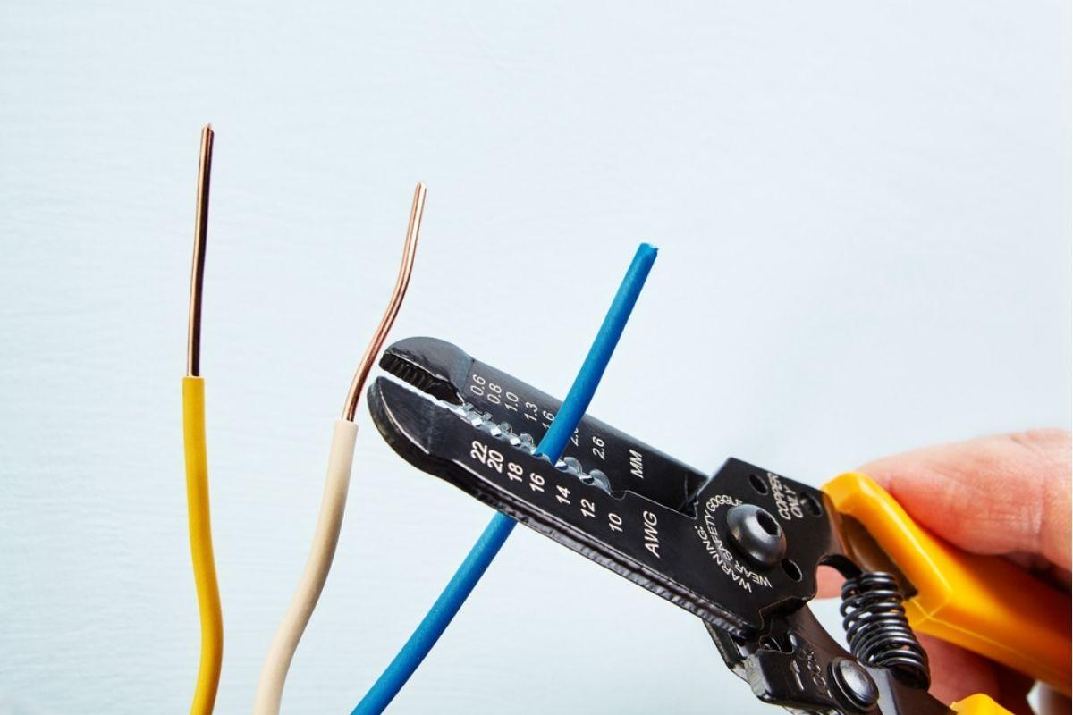 Use a wire stripper to strip the plastic sheath at the end of the wire about 2 – 3cm
Step 2: Identify the connection points
Proceed to connect each wire to the correct terminal on the circuit breaker or power source:
- Wire L (Brown, Black, Red, Gray, Orange,…) connects to the live phase terminal (L) of the circuit breaker.
- Wire N (Sky Blue, White) connects to the neutral terminal (N).
- Wire PE (Yellow Green) connects to the grounding wire of the house.
Step 3: Secure the wire ends
Insert the wire ends into the connection points on the circuit breaker, then use a screwdriver to tighten the screws to secure them. It is advisable to check by gently pulling the wires to ensure they are held firmly and not loose.
Step 4: Check
After completing, turn on the power and try to start the cooker. You can use a voltage tester to lightly touch the metal casing of the cooker to check, ensuring there is no leakage before use.
How to connect the 4-wire induction cooker
The 4-wire induction cooker often appears in some imported cooker models, where the power wire consists of two phase wires (L), one neutral wire (N), and one grounding wire (PE). When installed in a single-phase 220V electrical system in Vietnam, it is necessary to connect the two phase wires together before connecting to the power source. The steps are as follows:
Step 1: Prepare the wire ends
Use a wire stripper to strip the insulation of the 4 wires about 2 – 3 cm to expose the copper core. For wire L (Brown, Black, Red, Gray, Orange,…), it is advisable to strip a little longer for easier twisting.
Step 2: Twist the phase wires together
Twist the 2 L wires together to form a common wire, which is the phase wire L after twisting. The other two wires remain unchanged, the N wire (Sky Blue) is kept separate, and the PE wire (Yellow Green) is kept separate.
Step 3: Connect to the circuit breaker
- Insert the twisted pair of L wires into the L terminal of the circuit breaker.
- Insert the N wire (Sky Blue, White) into the N terminal.
- Insert the PE wire (Yellow Green) into the PE wire (ground).
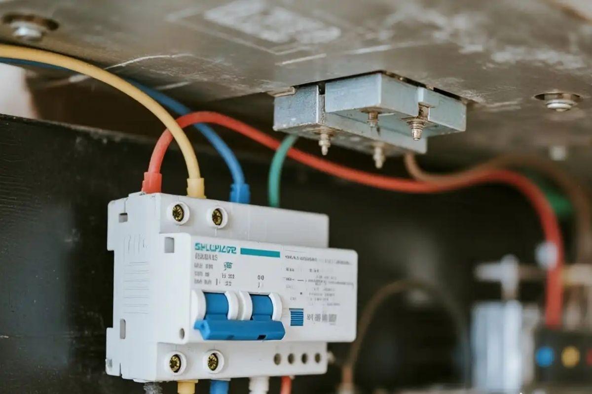 Connect the induction cooker’s wires to the corresponding terminals of the circuit breaker
Step 4: Insulate and check operation
Use electrical tape to tightly wrap the twisted wire connection points to prevent exposure of the copper core. Then turn on the power, turn on the cooker at all cooking zones to ensure the cooker operates stably and there is no overheating of wires or leakage.
How to connect the 5-wire induction cooker
The 5-wire induction cooker often appears in high-capacity imported models, designed to be used with various electrical standards. When installed in a single-phase 220V electrical system in Vietnam, understanding How to connect the 5-wire induction cooker and performing the twisting of the two pairs of wires before connecting to the circuit breaker is a prerequisite for the cooker to operate stably.
Step 1: Prepare the wire ends
Use scissors to cut all 5 wires. Then, use a wire stripper to strip the insulation of the 5 wires about 2 – 3 cm to expose the copper core. Twist each wire core tightly to prevent fraying when connecting. For high-capacity cookers, it is advisable to use terminals to crimp the wire ends for a more secure connection.
Step 2: Twist the two pairs of wires according to function
- Twist the 2 L wires (Brown, Black, Red, Gray, Orange,…) together to form the live phase wire L.
- Twist the 2 N wires (Sky Blue, White) together to form the neutral wire N.
- Keep the PE wire (Yellow Green) unchanged.
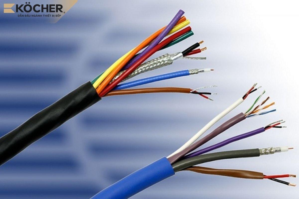 Twist the pairs of wires according to their functions together
Step 3: Secure to the circuit breaker
- The twisted pair of L wires connects to the L terminal of the circuit breaker.
- The twisted pair of N wires connects to the N terminal of the circuit breaker.
- The PE wire (Yellow Green) connects to the PE wire.
Then, use electrical tape to wrap each pair of wires that have just been connected.
Step 4: Check the load
Plug in the power and use a voltage tester to touch the area just connected; if the tester does not light up, it means there is no leakage at the connection area, and you have successfully connected.
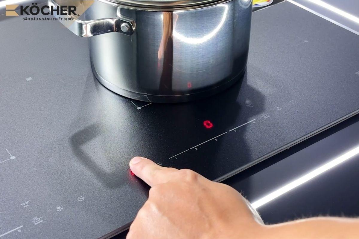 Turn on the cooker to check if it is powered and if there is any leakage
7 important notes when connecting the induction cooker’s wiring
When connecting the induction cooker’s wiring, you need to pay attention to the following 7 points to ensure the cooker operates stably and lasts long:
- Check that the Ampere (A) rating of the circuit breaker (CB) is greater than or equal to the maximum power of the cooker to avoid electrical overload. For example: A 4000W cooker should use a 20A – 25A CB, a 7000W cooker needs a 30A – 40A CB.
- Always use a voltage tester to accurately identify the live wire and neutral wire before connecting. Do not rely solely on wire color as some imported cookers may use different wire colors than usual.
- Technicians must strictly adhere to the grounding wire connection method for induction cookers by installing dedicated grounding rods or directly connecting the yellow-green PE wire to the building’s grounding system to eliminate stray electricity running on the glass surface and the machine casing.
- Run the electrical wires through conduits or tubes when wiring in the kitchen cabinet to limit rodent bites, moisture, and protect the insulation layer.
- Place the circuit breaker and connection points at least 50cm away from water sources to reduce the risk of short circuits when the kitchen area is damp.
- Do not arbitrarily cut short or replace the cooker’s power wire as the accompanying wire has been calculated by the manufacturer for a suitable cross-section for the device’s power.
- Prioritize crimping the wire ends with terminals before connecting to the circuit breaker to increase stability and reduce the risk of loose wires or arcing at the connection point.
- Disconnect the power and periodically check the connection points every 6 – 12 months of use, tightening any loose screws to ensure stable electrical contact.
Above is a detailed step-by-step guide on how to connect the induction cooker with 5 wires, 4 wires, and 3 wires along with 7 notes when performing. We hope this guide can help you successfully connect the induction cooker at home.
Customers choosing Köcher brand induction cookers will be supported by the company’s professional technicians throughout the installation and usage process. Check out Köcher’s products here.
|
Köcher induction cookers pioneer German technology – For detailed product information, please contact:
|